Pressure Alteration Test On Coolant Circuit

Pressure testing
cooling circuits
Electric vehicles (EVs) differ significantly from internal combustion engine-powered vehicles and the design of many components. Although energy efficiency is also extremely important in a combustion engine, energy and thermal management in an electric vehicle are of paramount importance for the vehicle’s usability and long-distance performance.
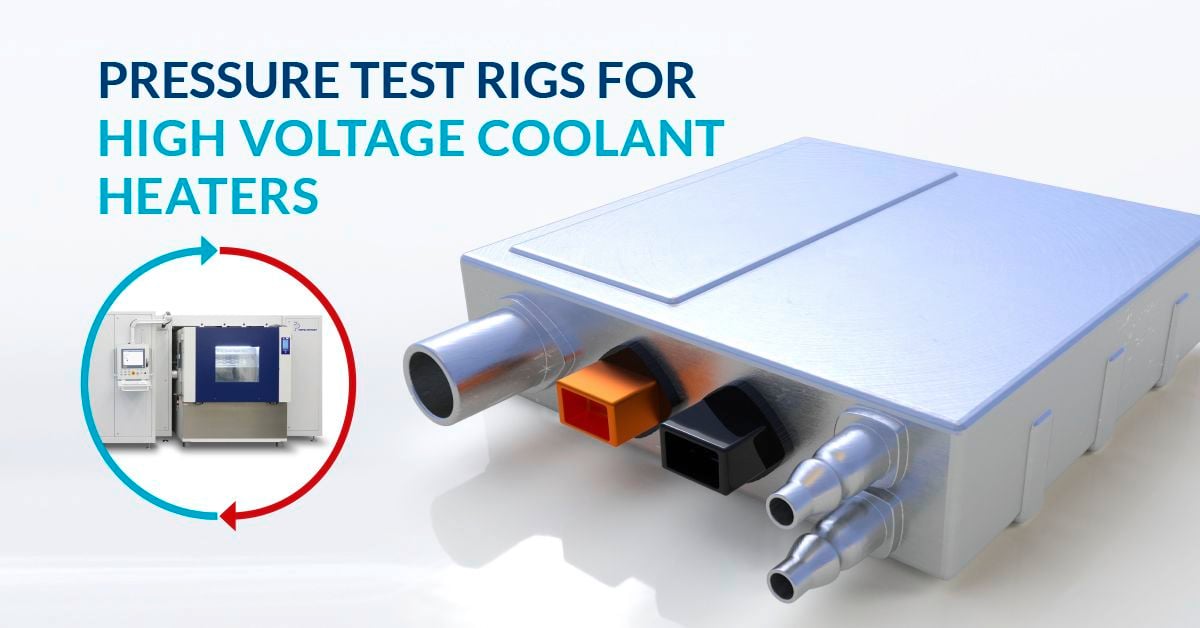
As technology advances, vehicles are full of electronic systems that require cooling. Electronic control units (ECUs), batteries, AC/DC converters, high-voltage coolant heaters, power module cooling plates, high-voltage water heaters, PTC heaters and many other components mandate heating and cooling circuits to ensure functionality under various temperature and climate conditions. Cooling circuits are often equipped with an inlet and an outlet to create coolant (or oil) flow through the circuit. The flow can be between 20 l/min and 60 l/min. To achieve a flow pressure, the circuit is pressurized.
Test Procedure
M-07 | GS95024-3 | VW8000 | GMW14193
There are many test standards that define the procedure for a pressure cycle test for coolant circuits. However, we have found that the predominant customer search right now is for the M-07; including the pressure cycle test, overpressure and underpressure test (vacuum). Our test benches cover a wide variety of standards, but we will describe the M-07 as an example in this blog post, as it is similar to other standards and has a lot of overlap.
The M-07 describes the testing requirements and processes that must be met for component validation. As previously described, components are subjected to alternating pressure with coolant while being subjected to dynamic ambient and media temperatures to simulate heating requirements during component operation.

In addition, the circuits and components are subjected to negative pressures when the cooling system is filled. (The P+P test benches can complete negative pressures with both air/gas and coolant.)
It is important for manufacturers to put their components on the test bench to prove the mechanical strength and tightness of the components exposed to pressure fluctuations. (p. 34, GS 95024-3-1, 08-2019) The M-07 standard and test procedure are divided into three parts. It is important to note that coolant is required as the test medium (e.g. 50% by volume of ethylene glycol, 50% by volume of water). If the standard you follow states otherwise please let us know as we can adapt and test the system for other fluid compositions if necessary.
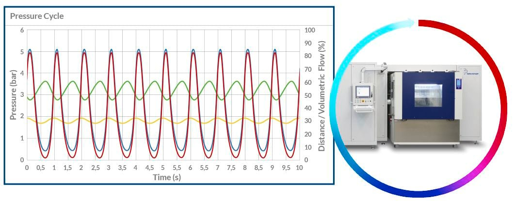
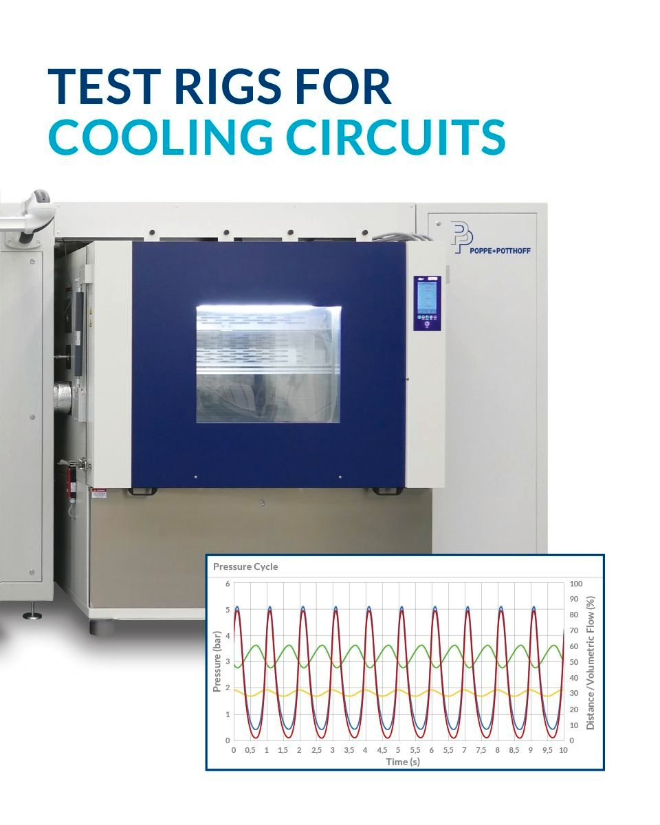
Part 1 of M-07 demands a pressure pulsation test with a minimum test pressure (pmin) of 0.5 (-0.1) bar and a maximum pressure (pmax) of 2.0 (+0.1) bar at a frequency of 25-35 1/min alternating pressure. 100,000 cycles are required, with temperatures varying. We are aware that your component may require higher pressures, more cycles or different frequencies. Our flexible systems are based on your specifications and meet industry standards. A component can be tested over several weeks or months.

The second part of the procedure requires an overpressure test with a test pressure of 4.0 (+0.1) bar with a total test duration of 1 hour under different temperature conditions.
The third and last part of the M-07 test calls for a negative pressure test (negative) with a test pressure of -0.01 bar, with a test duration of 30 minutes. It is important to note that this is completed by a test without a test medium but with air or gas. However, P+P has a solution containing glycol at 0.5-1 bar, which is below atmospheric pressure and is therefore considered negative pressure.
Would you like to learn more about our test benches that enable coolant circuit testing and other pressure swing test applications? Contact us today.
Other similar test norms are GS 95024-3-1 M-07, MBN 10306 M-07, GMW141913 and VW80000 M-07 (VW)

